Monday, February 24, 2014

Create a bolt

Create the following in CAD:
Diameter = .25"
Length = 1.5 inches

28 threads / inch
UN
Flat, combined head

Cylinder: D = .25, h = 1.5


Helix:
R = (.25/2) .125,
h = 1.5,
# turns = 28 + 14 = 42


Create a triangle with sides that are .0357 long
(1.5"tall/42 turns = .035714")
Rotate the triangle onto one of the ends of the helix with the point going in, and perpendicular. (xlines added to try and show orientation)

Hint: Rotate the Helix so that the end is on one of the coordinates, then line the triangle up with the coordinates too. 

Keep the helix centered on 0,0,0, as you will not be able to snap objects to the center of it in the future.


Join the sides of the triangle together, and try to sweep it.  If you have trouble sweeping it, fillet the corners so they don't overlap with one another.  (Fillet corner w/ r = .003)


Copy yout triangle (in case you need it later)

Sweep triangle along Helix


Move cylinder onto Helix, subtract Helix from cylinder.  Keep everything centered around 0,0,0 to get it all lined up.


If you get everything lined up right, you should be able to see pointed triangles on a sectional view.


Head:

Use a cone with r = .25, height = .25, centered on one of the ends.  Union.


Hex nut + washer

Polygon, 6 sides, c, r = 0.25
extrude h = .25
find center - connect corners with lines.


Copy bolt, snap to center, subtract bolt out from center of nut


Draw a circle on top, create a cone.


Cone: r = .25, h = .25


 Use the blue arrow on the top of the cone to pull the center out:


Pull open until the cone clips off the corners.

 Copy the cone for use on the other side

 Use "Intersect" to clip off the corners.


 Clip off corners on other side.


Create a washer


Done!

Now, Choose a different style head, thread, and nut, and create another one!


Wednesday, February 19, 2014

Sectional Views

In this class, we will learn how to make sectional views, and play around with more of the tools in the layout menu.

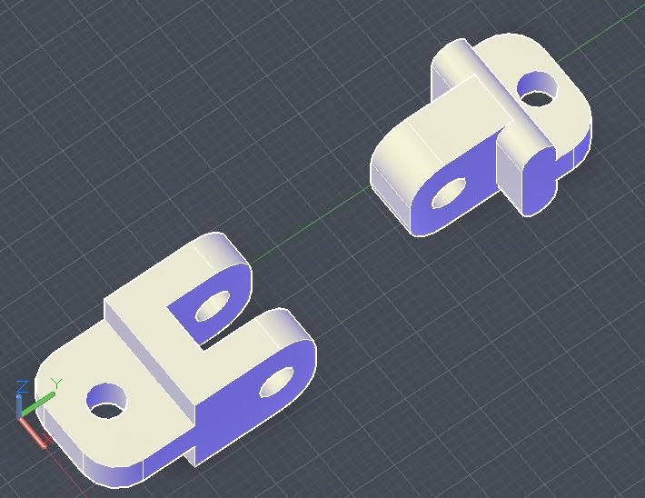
First, Create this:


Here are some coordinates to help you out:
Z direction heights are 2,4, and 6.


Remember to save your work often!!


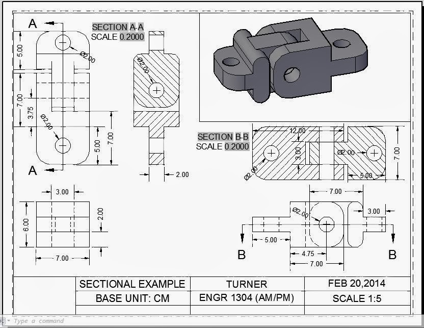
Open up your title block (ANSI A), erase the viewport, and use VIEWBASE  like before.  To leave room for sectional views, change the viewbase scale to 1:5 (instead of 1:4) while you are creating it. 


Find the sectional views in the layout panel, create a full sectional.  Snap to the center of your solid.


Note: You can always grab your selection line by the blue grips, and move it around later.

Next, add a viewport to show the isometric view in the upper right hand corner.  Right click on the section labels, open up the properties box, and change the text size, move them to a good spot.


Add dimensions. 


Done!  Print it out, and turn it in.

In another layout, explore the "Detail" views.  "detail" is in the ribbon in the Layout tab, right next to sectional views.  Start with viewbase again, and then select rectangular or circular portions to create a detailed view of.


Also, check out the styles and settings options:


Open up the menu, hit "modify" and check out everything that is in it.  Change your font styles, arrow styles and colors, etc.


There are many different hatch patterns, select a few different ones, and see the previews of your selection.


Next, check out the "Edit Components" options:


If there are multiple parts, you can select to either section a part, or not. 


Create a new sectional view where one of the parts is not selected, and see the new view.  (Below, the top part is not hatched because it was not sectioned.)


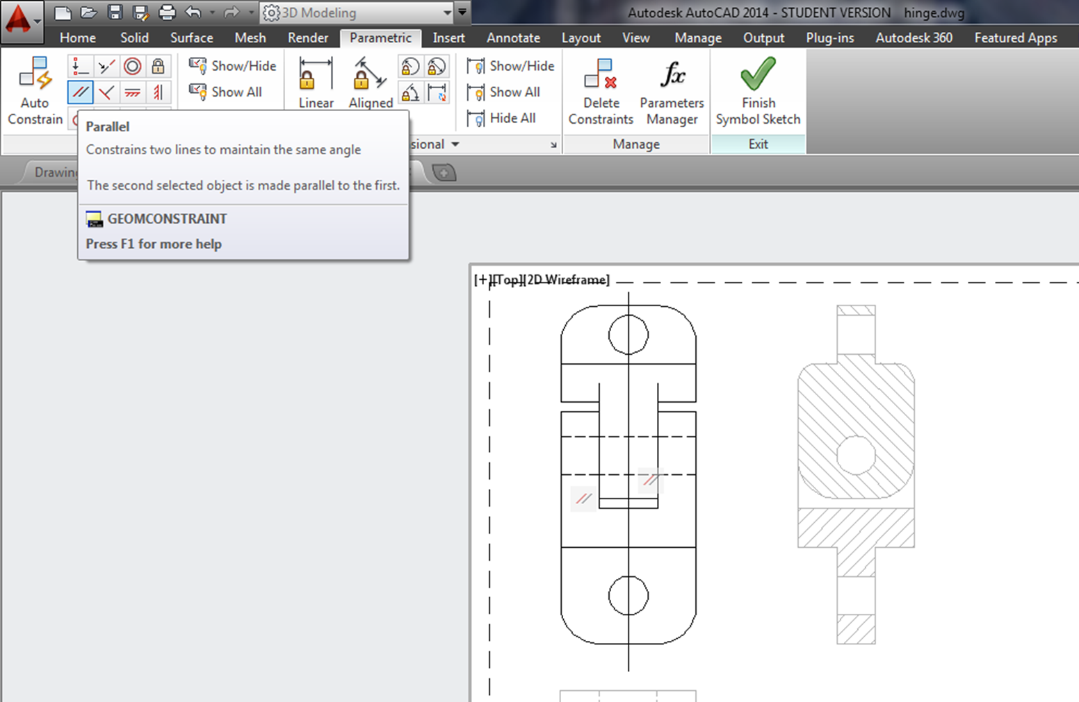
Next, use the "symbol sketch" tool to line up your sectional views to the model:


You can set the sectional views to be parallel, perpendicular, etc. to any surface, Just read the command line, and play around with it!


Monday, February 17, 2014

Working with Surfaces


Let's start by working with multiple viewports in the model space.

Type: VIEWPOORTS
select: Two: Verticle

This will allow you to see two simultaneous views of your object at once for a more complete visualization of what you are doing.  Your screen should now look like this:


Next, we're going to create a surface, and go through the different tools used with surfaces.  From the AutoCAD help menu:


Let's start with an extruded surface, and then change it into a NURBS.

Draw a PLINE, and switch one of your viewports to SW Isometric, while keeping the other viewport as a Top view.

Note: I selected "A" for arc after starting up the pline command, just watch the command line!


Extrude your PLINE to create a surface.  Either type "EXTRUDE" in your command line, or choose Extrude from your 3D Tools Modeling menu.


Select your object, right click on it, and display it's properties - you will see the "Surface Type" listed as "Extrusion".


You can also hover your mouse over a surface to display what type of surface it is:


Experiment with the blue grips and gizmos to change the shape of your surface.  Notice that because this is an extruded / procedural surface, everything is connected and changes size and shape together.  In the Top view, you can see that the xy depth of your pline is constant throughout the object.

Pay attention to the grips - square, vs. triangle, and what they do.


Change from "Drafting and Annotation" into the "3D Modeling" space. Open the Surface menu, select "Convert to NURBS", follow the command prompts to convert your extruded surface into a NURB surface:


If you hover your mouse over your surface, it should show NURBS surface:


Now that your surface is NURBS, experiment with the blue grips and gizmos.  You will find that you now have more editing options.

You can select individual pieces of your line, kind of like if you had exploded it:


Pull all of the pieces of your line apart.


BLEND

Use the Blend command to join two of your line segments


SURFBLEND Select first surface edges to blend or [Chain]:
 - select surface, hit enter


SURFBLEND Select second surface edges to blend or [Chain]:
 - select surface, hit enter


AutoCAD now connects the two separate surfaces to one another.
Before accepting the new surface, play around with the options in the command line:

SURFACEBLEND Press Enter to accept the blend surface or [CONtinuity Bulge magnitude]:

select CON, choose the different options to see what happens.
G0 for both surfaces gives you a straight connection:


G1 gives you a curve:


G2 gives you a larger curve:


Now, select "Bulge magnitude", change the bulge on each side to be larger or smaller.

Bulge of 0.0 pn each side gives you the G0 from continuity. 

Vary your bulge between .2:


.8


1.5


CV Edit Bar:
Hover your mouse over the CV Edit Bar tool long enough for the large window demo to pop up.


Use the CV Edit Bar to reshape one of your surfaces. 
Note: if the surface has a high curvature, you will need to follow the prompts to edit it.  Try starting the CV Edit command with a lower curvature surface (ie, not the half circle)

Experiment with the different grips and movement options in the CV Edit menu:


.
Select objects, right click on them, experiment with the "rotate" option.


Move, rotate, and blend your surfaces to create a closed loop.

Watch the command line!  Selecting blue grips, or lines will give you different options.
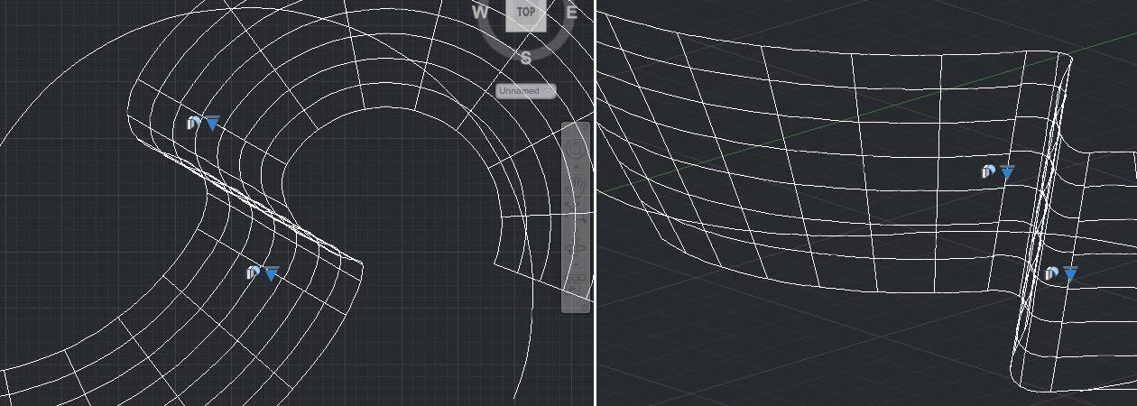


PATCH


Create a closed pline, extrude it, and create something to try out the patch command. 


Note: You have to have a nice, continuous edge to use the patch command.
SURFOFFSET - hold your mouse over the offset button, and watch the short animation.


Offset your surface:
note - offset has trouble with some bounded areas, in this example, it was unable to offset the patch that I created earlier.


SCULPT

Next, let's explore the SCULPT command:


Hover your mouse over the command, watch the animation.


PLANAR command:


I created two rectangles, "MOVE" ed them up off the xy plane to heights that intersect my surfaces, then used "PLANAR" to form enclosing surfaces.


Now that you have a region bounded by surfaces, try out the sculpt command:


SLICE your object in half to see that you no longer have surfaces, but now have a 3D solid.


Start a new drawing area, Create some lines to use the "NETWORK" command.

First, hover your mouse over the icon, and read the description.


next, create some PLINE's to NETWORK together.  Use the OFFSET, COPY, and MOVE commands.  Your PLINE's will need to be smooth and continuous in order to network them.


Experiment with what lines you select - first, try to NETWORK the lower left square by selecting only two lines in each direction.  See what happens, then undo it to try a different selection.  Try selecting 4 lines in one direction, and only two lines in another direction. 


Play around with some of the other surface editing tools - just read through the help, and watch the command line!

SURFACE EXTEND


SURFACE TRIM


Use the Surface commands to create the objects on pg 81, and pg 85.

Pg 81:
Sketch the views on the xy plane, create surfaces, then create solids, then rotate and move all of the sides into place.


Pg 85: Use whatever is easiest for you, but make sure the entire part is a solid at the end if you use surfaces to create it.  Dimension your work.