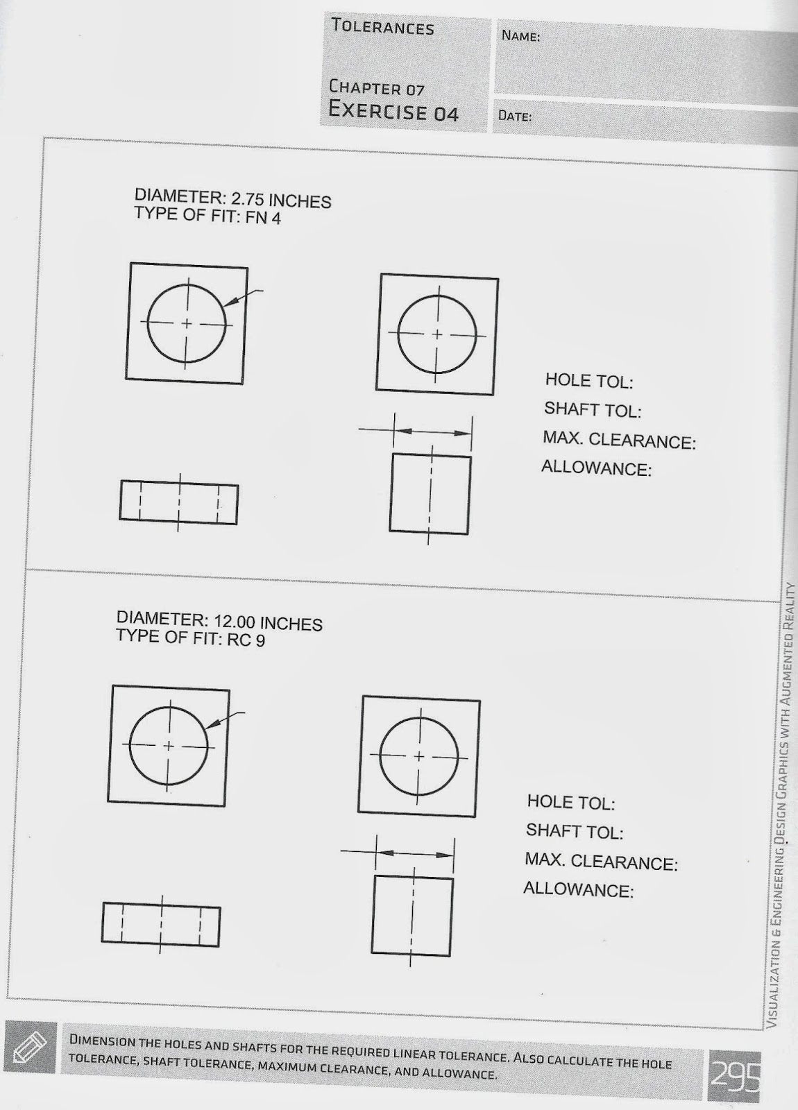
Tolerance – The acceptable error allowed when machining a dimension, or the total amount a dimension may vary.
All dimensions in a drawing have a tolerance.
Some dimensions require smaller tolerances than others.
Example: If the diameter is
Some dimensions require smaller tolerances than others.
Example: If the diameter is
ᴓ2.00inches ± 0.03, it needs to be machined between 1.97 and 2.03 inches.
Error -
Smaller allowable error = larger manufacturing cost

Error -
Smaller allowable error = larger manufacturing cost

Economics of Machining – 4 factors:
1. Machining Cost
labor + overhead, total time per piece.
increased speed = reduced cost
1. Machining Cost
labor + overhead, total time per piece.
increased speed = reduced cost
2. Material Cost
3. Tool Cost
increased speed = more costly tools
(tool life decreases with speed)
improved lubricants and coatings extend tool life
increased speed = more costly tools
(tool life decreases with speed)
improved lubricants and coatings extend tool life
4. Set-up costs
Accuracy - How close to a true value
Precision – how repeatable results are
Acceptable - Does the part serve it's function?
Interchangeable parts - what systems will it be used in?
3 Different forms to express tolerance:
Acceptable - Does the part serve it's function?
Interchangeable parts - what systems will it be used in?
3 Different forms to express tolerance:

A. Unilateral (asymmetrical) range of values that deviate in only one direction, +x, -y.
B. Bilateral (symmetric) equal deviations in the part ± x.
C. Limit - provide max and min values: Xmax/Xmin
Two types of tolerances: 1. Dimensional - accuracy in terms of size and dimensions
2. Geometric - accuracy in terms of shapes, locations, and profiles.
General tolerances:
Define acceptable level of error for all dimensions in a drawing that are not individually identified.
Typically in bilateral form
Found in title block, or added as a note to drawing.
Linear Tolerances:
Specific tolerance for a particular feature that is different than the general tolerance.

Matching or Mating Parts:
Components that are designed to fit to one another within a prescribed degree of accuracy.


 4 parameters for mating parts:
1. Tolerance of the first mating part
2. Tolerance of the second mating part
3. Allowance - maximum amount of interference (tightest fit) between two mating parts. Occurs when:
Hole - machined to smallest size
Shaft - machined to largest size
Allowance = Smallest possible Hole (SH) - Largest Possible shaft (LS)
4. Maximum clearance - Max space between two mating parts, or loosest fit.
Maximum clearance = Largest possible Hole (LH) - Smallest Possible Shaft (SS)


~~~~~~~~~~~~~~~~~~~~~~~~~~~~~~~~~~~~~~~~~~~~~~
Example for a shaft and pulley:

Shaft
upper limit: ᴓ.4975
lower limit: ᴓ.4955
Shaft tolerance (ST) = 0.4975-0.4955 = 0.0020
.
Hole in pulley:
upper limit: ᴓ.5004
lower limit: ᴓ.5000
Hole tolerance (HT) is 0.5004-0.5000 = 0.0004.
Allowance = 0.5000 (SH) - 0.4975 (LS) = 0.0025
Maximum Clearance = 0.5004 (LH) - 0.4955 (SS) = 0.0049
~~~~~~~~~~~~~~~~~~~~~~~~~~~~~~~~~~~~~~~~~~~~~~~~~~~~


Calculations for Tolerance For mating parts:
.1. Basic-Hole:
diameter = minimum hole size = constant,
dimensions and tolerances calculated using min hole size.
convenient for manufacturing - easier to adjust the size of a shaft (grind it down) than to adjust the size of the hole.
Use min hole size - you can enlarge a hole, but if you drill it too large, you can't go back to make it smaller, so it's better to start out with it too small.
2. Basic-Shaft Systems
diameter = maximum shaft size
dimensions and tolerances calculated using max shaft size.
Used in textile industry, not as common as basic hole.
~~~~~~~~~~~~~~~~~~~~~~~~~~~~~~~~~~~~~~~~~~
Fit: Degree of tightness between mating parts.
Do parts need to slide freely within an assembly?
Do parts need to be held tightly together?
3 Types of Fits
1. Clearance Fit - LC - designed to have room (clearance) between parts. Shaft is always smaller than the hole.
(The piston in combustion engine is a clearance fit)

2. Interference Fit - LN, FN - forced, or press fit:
Diameter of shaft larger than hole, mating parts interfere with one another, both parts elastically deform.
Shrink fitting: outside is heated (expands), inside is cooled (contracts)

3. Transition Fit - LT - Two parts can either clear or interfere with one another. Allowance is negative or zero, maximum clearance is positive.
line fit - allowance = 0.

Fits

English Fits:
http://www.cobanengineering.com/Tolerances/ANSILimitsAndFits.asp
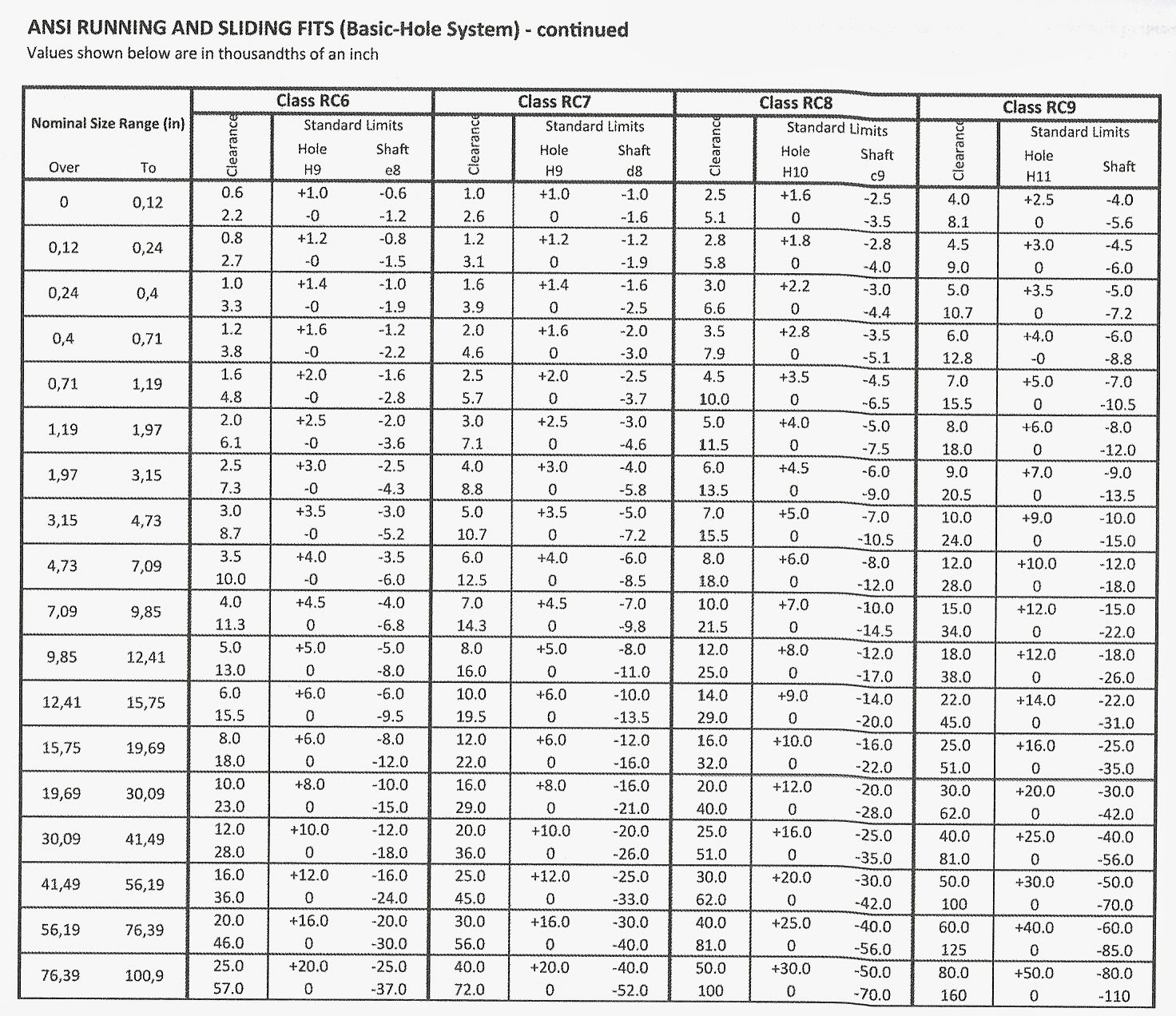
Fig 7.14 - example RC tolerance table
~~~~~~~~~~~~~~~~~~~~~~~~~~~~~~~~~~~~~~~~~~~


Example pg 276:
Find the tolerances for an RC2 cylindrical fit ᴓ3.00 hole/shaft assembly:
Hole tolerance = +0.0007 and 0
Shaft tolerance: -0.0004 and -0.0009
Add or subtract tolerances from the base diameter
Largest Hole (LH) = 3.00+.0007 = 3.0007
Smallest Hole (SH) = 3.00+ 0 = 3.0000
Largest Shaft (LS) = 3.00-.0004 = 2.9996
Smallest Shaft (SS) = 3.00-0.0009 = 2.9991
.Hole Tolerance = 3.0007 - 3.000 = .0007
Shaft tolerance = 2.9996-2.9991 = 0.0005
Max Clearance = 3.0007 - 2.9991 = 0.0016
Allowance = 3.0000 - 2.9996 = 0.0004

~~~~~~~~~~~~~~~~~~~~~~~~~~~~~~~~~~~~~~~~~
Metric Fits - 278
Complete Fit:
Two tolerance grades
1. Hole Tolerance
2. Shaft tolerance
Nomenclature example:
20H7/g6
20 = diameter in mm
H7 = hole tolerance
H = deviation
7 = IT grade
g6 = shaft tolerance
g = deviation
6 = IT grade


~~~~~~~~~~~~~~~~~~~~~~~~~~~~~~~~~~~~~~~~~~~~~~~~~~~~~~~~~~~~~~~~~
Example: Find a H7/s6 (Medium drive) cylindrical fit for a 10mm diameter hole/shaft assembly:
g6 = shaft tolerance
g = deviation
6 = IT grade


~~~~~~~~~~~~~~~~~~~~~~~~~~~~~~~~~~~~~~~~~~~~~~~~~~~~~~~~~~~~~~~~~
Example: Find a H7/s6 (Medium drive) cylindrical fit for a 10mm diameter hole/shaft assembly:
10H7/s6
Largest hole = 10.015
Smallest Hole = 10.00
Largest Shaft = 10.032
Smallest Shaft = 10.023
Hole Tolerance = 10.15-10 = 0.015
Shaft tolerance = 10.032-10.023 = 0.0009
Max clearance = 10.015-10.023 = -.008
Allowance (Min clearance) = 10-10.032 = -0.032
Max clearance = 10.015-10.023 = -.008
Allowance (Min clearance) = 10-10.032 = -0.032
~~~~~~~~~~~~~~~~~~~~~~~~~~~~~~~~~~~~~~~~~~~~~~~~~~~~~~~~~~~~~~~~~~~~~
Geometric Tolerances
Error in shape, form, location, and orientation.
Symbols for geometric tolerance:

Label in control frame:
Type of tolerance (// - make two sides parallel to one another)
Tolerance Value (0.15)
Reference point (A - the sides that are supposed to be parallel)
MMC - Maximum Material Condition
LMC - Least Material Condition
Manufacturing - Use large or small end of tolerance ranges to increase strength / decrease weight / etc.
,
Tolerances of Form:
Flatness & Roundness
Straightness &
Cylindricity: Combo of roundness and straightness
Profile Tolerance:
Error in arcs, curves, and irregular profiles.
Tolerance of profile & Orientation:
Parallelism & Perpendicularity
Position:
Concentricity:
Symmetry:
Runouts:Part revolved around axis

Set up an Excel spreadsheet, copy it for all the problems, so all you have to do is look up the #'s in the tables, and type them in.
Here's the first one:


Metric

Just do #1 and #2

:


