You're on last year's blog!
The new and improved blog is here:
http://e1304.blogspot.com/2014/06/syllabus.html
One more month, and this site will become null and void.
See you in class!
Wednesday, June 25, 2014
Monday, April 28, 2014
Final Exam Practice
Reminder:Sign up for your summer math classes ASAP!! If enrollment is low, these classes will be dropped and you will lose your opportunity to sign up.
Tuesday April 29th
Finish up your semester project & any other assignments.
http://engr1304.blogspot.com/2014/03/engineering-project-report-presentation.html
Thursday May 1st
Semester project and presentations are due
Final Exam Schedule:
http://www.lonestar.edu/examschedule.htm
1304 Tu/Th 9:30-12:30 class
- exam will be Th May 8th from 9:30-11:20
1304 Tu/Th 6:00-8:50 class
- exam will be Tu May 6th from 5:30-7:20
The final exam will consist of two parts:
{art 1: Written questions:
1. A tolerance worksheet with a few problems similar to those on pg 289-305
link
2. Concept questions from architectural engineering
List the four principal control layers for a wall,
discuss insulation & building energy efficiency,
3 main types of blueprints:
Plan View, Elevation View, section view
http://engr1304.blogspot.com/2014/03/walls-roof-stairs.html
http://engr1304.blogspot.com/2014/03/blueprint-reading.html
3. Concept questions over an internal combustion engine:
- what are the 4 strokes for an internal combustion engine?
- Name the main parts of an engine
- Name sources of energy loss
http://engr1304.blogspot.com/2014/04/gas-power-cycles.html
4. Concept questions over FEA -
http://engr1304.blogspot.com/2014/04/fea.html
CAD / Inventor Assembly Make a complete set of working drawings for a simple assembly in either Inventor or AutoCAD. Your set of working drawings should have:
a) An exploded assembly drawing with a parts list, balloons with leader lines.
http://engr1304.blogspot.com/2014/04/working-drawings-chapter-9.html
b) Individual parts with dimensions and tolerances labeled.
http://engr1304.blogspot.com/2014/04/geometric-tolerances-in-cad.html
It will be an open book / open internet test so that you can look up the symbols and use the tolerance tables in your book or on the webpage.
Practice for Test & Tolerances in Inventor

Make a birdhouse similar to the one on pg 343-346Note: Just "similar", it doesn't have to be exact - change it to use the same size screws through the entire project so you don't have to worry about different hole sizes etc.

(I made everything out of different types of wood etc. so you could more easily see the different parts)

 Example hinge:


To do this in Inventor:Use "Project Geometry" to line up the holes for the screws.

 3. Create View → open up your assembly file (click on the little folder on the right hand side of your file) → open
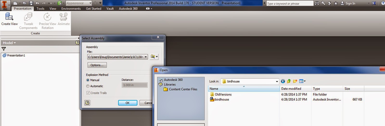
4. You can try to automatically explode it, but this does not always work out so well (especially when you have a lot of parts).... so select "Manual".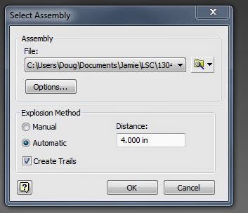
5. Tweak Components →Components →choose a part → Direction →click on a face and a direction, grab and pull it away, create a trail →"close" when you are done.
Note: You can select more than one component at a time, so you can move screws together etc. and you can also move in one direction, then click "x , y, or z", and move in another direction before closing.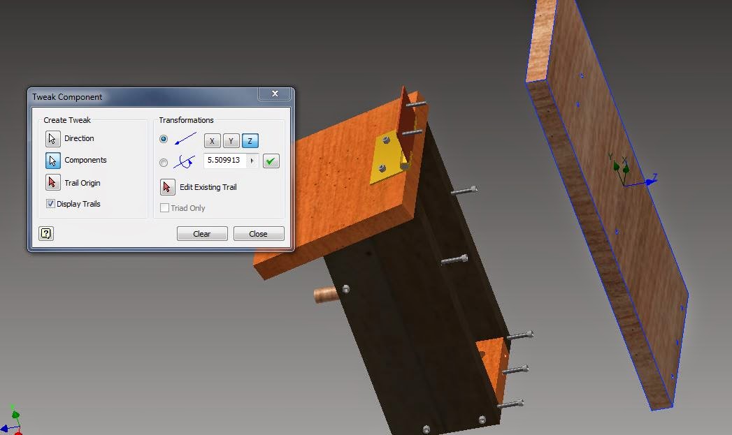
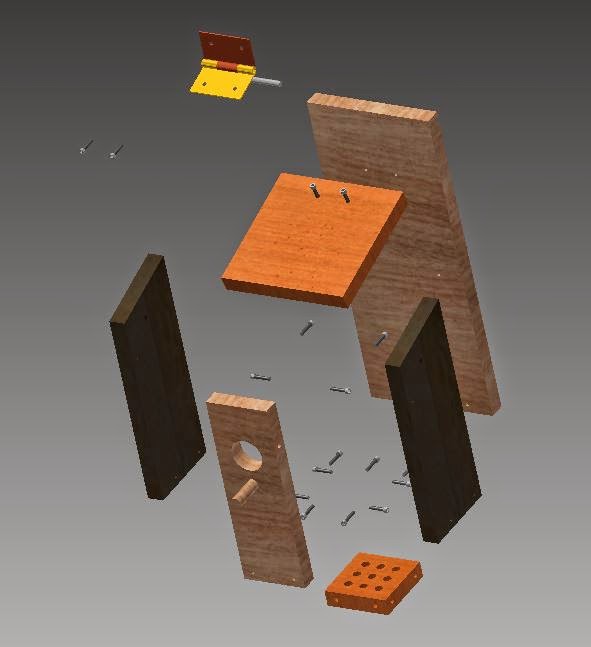
6. Click "animate" to see your components coming exploding or coming together, then save it.
7. Create a set of working drawings:
Set up your sheets like you did before - link
only this time, open up multiple sheets:
Sheet Format → Choose a size →right click, New Sheet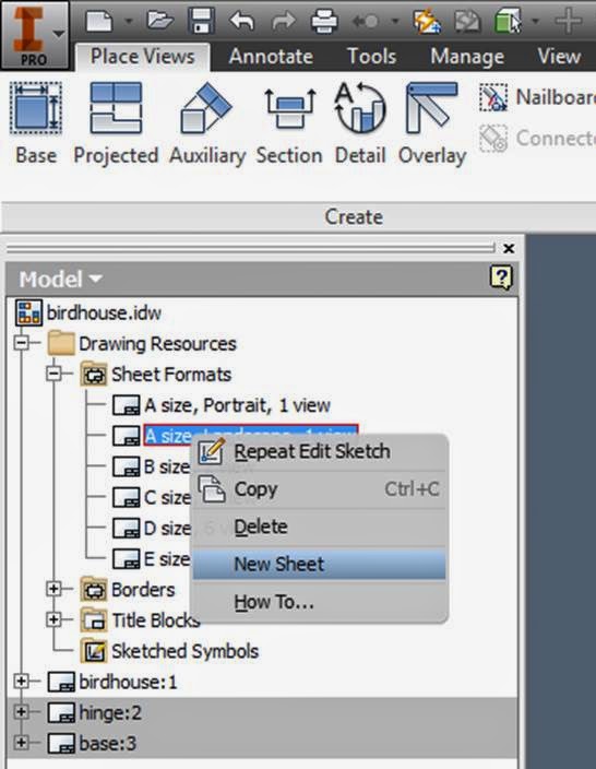
Create all of the diagrams that you need to,
8. Create a Parts list, Balloons, and a PDF etc. for your exploded view:
In your new blank sheet:
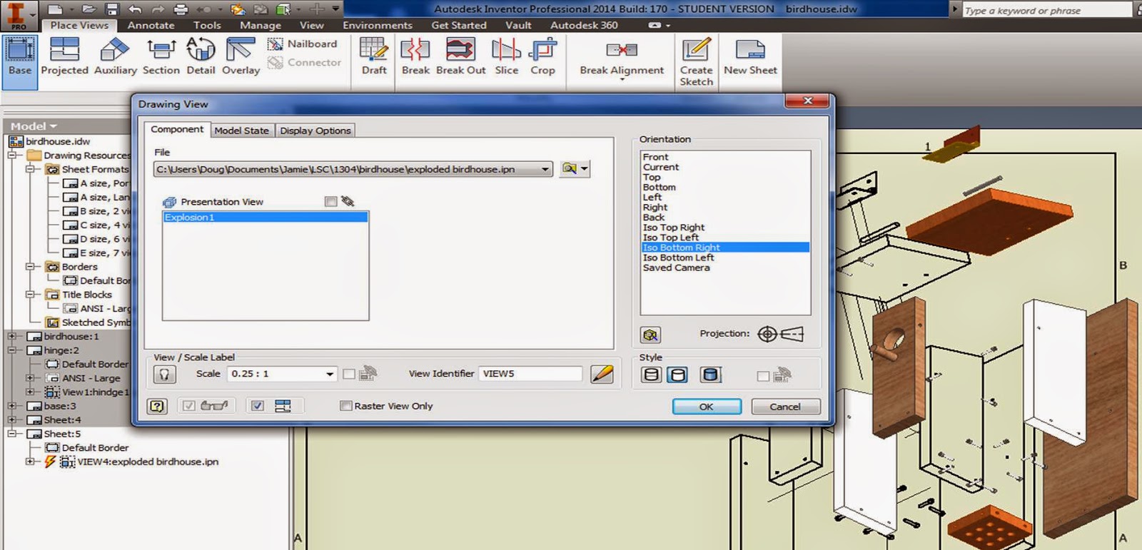
Base view → File (click the magnifying glass, and find your ipn exploded view → change the scale, change the view orientation.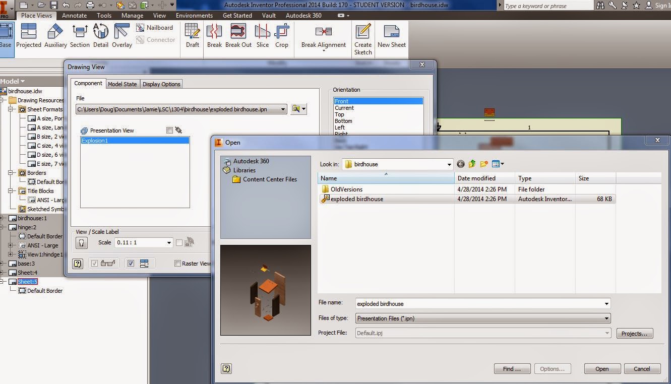
Create a Parts list:
Annotate → Parts List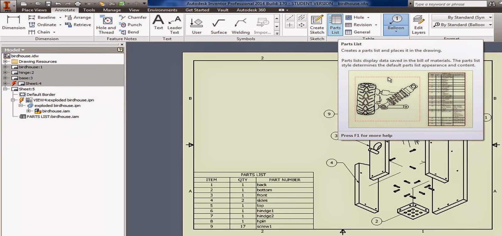
Click your parts list onto the page.
Double click on it to edit what columns and info it shows:
The upper left hand icon lets you add or remove properties to your parts list: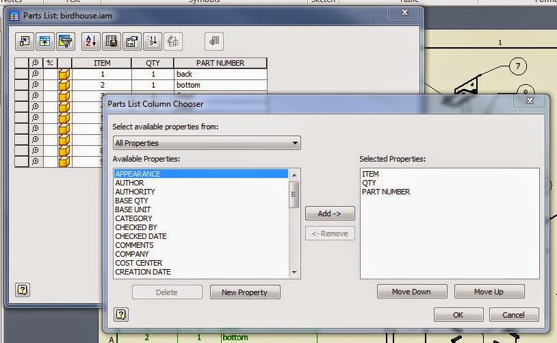
Then add your bubble part numbers:
It will automatically insert the correct number when you click on a part.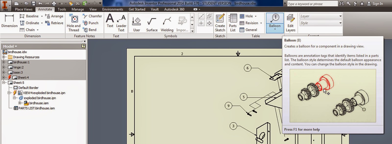
Youtubes going through working drawings in Inventor:
https://www.youtube.com/watch?v=XO2lE9zmhRU
https://www.youtube.com/watch?v=NBQXzL2tOGQ#t=39
You can decide to do all of this in CAD or in Inventor on the test.
Tuesday April 29th
Finish up your semester project & any other assignments.
http://engr1304.blogspot.com/2014/03/engineering-project-report-presentation.html
Thursday May 1st
Semester project and presentations are due
Final Exam Schedule:
http://www.lonestar.edu/examschedule.htm
1304 Tu/Th 9:30-12:30 class
- exam will be Th May 8th from 9:30-11:20
1304 Tu/Th 6:00-8:50 class
- exam will be Tu May 6th from 5:30-7:20
The final exam will consist of two parts:
{art 1: Written questions:
1. A tolerance worksheet with a few problems similar to those on pg 289-305
link
2. Concept questions from architectural engineering
List the four principal control layers for a wall,
- a rain control layer
- an air control layer
- a vapor control layer
- a thermal control layer
discuss insulation & building energy efficiency,
3 main types of blueprints:
Plan View, Elevation View, section view
http://engr1304.blogspot.com/2014/03/walls-roof-stairs.html
http://engr1304.blogspot.com/2014/03/blueprint-reading.html
3. Concept questions over an internal combustion engine:
- what are the 4 strokes for an internal combustion engine?
- Name the main parts of an engine
- Name sources of energy loss
http://engr1304.blogspot.com/2014/04/gas-power-cycles.html
4. Concept questions over FEA -
http://engr1304.blogspot.com/2014/04/fea.html
CAD / Inventor Assembly Make a complete set of working drawings for a simple assembly in either Inventor or AutoCAD. Your set of working drawings should have:
a) An exploded assembly drawing with a parts list, balloons with leader lines.
http://engr1304.blogspot.com/2014/04/working-drawings-chapter-9.html
b) Individual parts with dimensions and tolerances labeled.
http://engr1304.blogspot.com/2014/04/geometric-tolerances-in-cad.html
It will be an open book / open internet test so that you can look up the symbols and use the tolerance tables in your book or on the webpage.
Practice for Test & Tolerances in Inventor
Make a birdhouse similar to the one on pg 343-346Note: Just "similar", it doesn't have to be exact - change it to use the same size screws through the entire project so you don't have to worry about different hole sizes etc.
(I made everything out of different types of wood etc. so you could more easily see the different parts)
Pages out of book:

Put all of your parts together in an assembly, then save and close all of your parts.
Double click on one of the parts in your assembly, then open up the sketch of that part from the modeling window (double click on the sketch you want to edit)
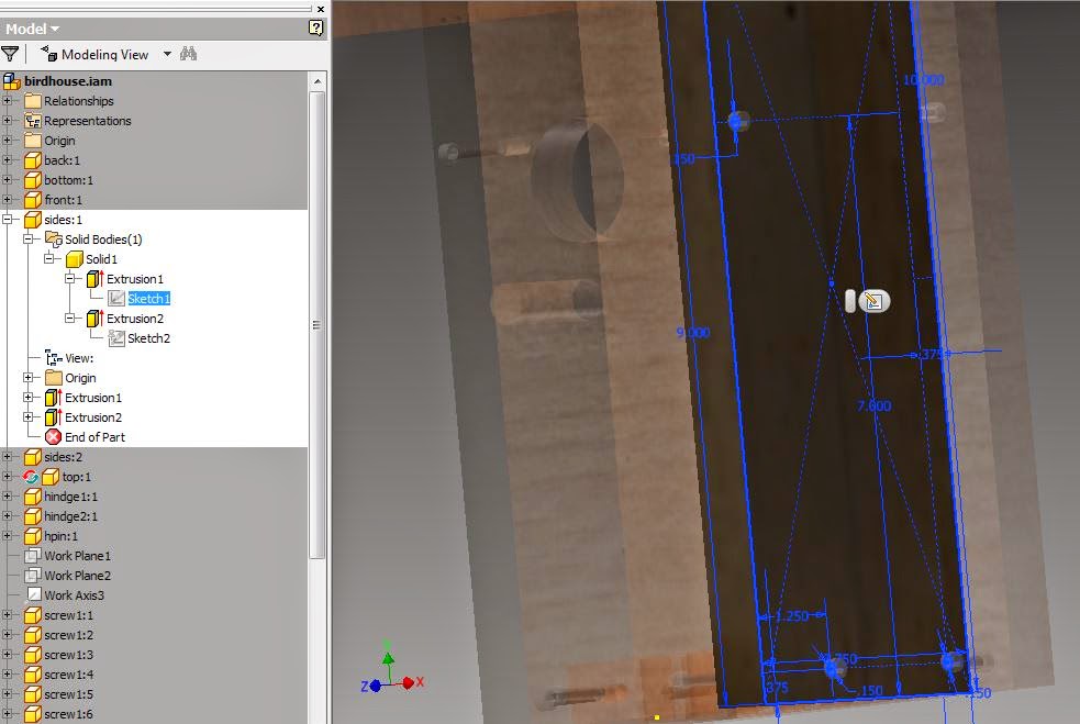
Choose "Project Geometry" from your sketching tools, then click on the holes in other parts, and project them onto the sketching plane for the part you are working on.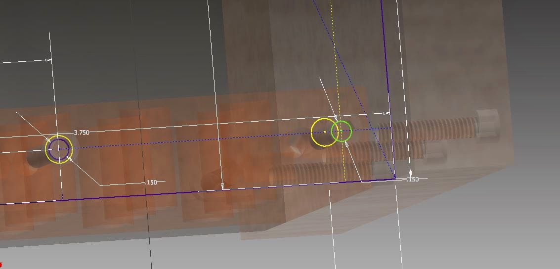
Move the hole from your sketches to line up with one another (note - you might have to turn off some of your constraints, or use the move command to do this)
Then "Finish Sketch" and "Return" to get back to where you were.
Save
Making an exploded view in Inventor:
1. Assemble all of your parts so that they are all fully constrained.
2. New → Presentation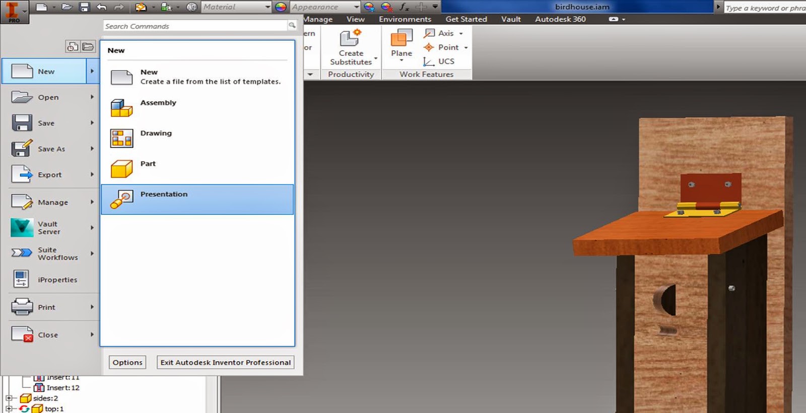
5. Tweak Components →Components →choose a part → Direction →click on a face and a direction, grab and pull it away, create a trail →"close" when you are done.
Note: You can select more than one component at a time, so you can move screws together etc. and you can also move in one direction, then click "x , y, or z", and move in another direction before closing.
6. Click "animate" to see your components coming exploding or coming together, then save it.
7. Create a set of working drawings:
Set up your sheets like you did before - link
only this time, open up multiple sheets:
Sheet Format → Choose a size →right click, New Sheet
Create all of the diagrams that you need to,
8. Create a Parts list, Balloons, and a PDF etc. for your exploded view:
In your new blank sheet:
Base view → File (click the magnifying glass, and find your ipn exploded view → change the scale, change the view orientation.
Create a Parts list:
Annotate → Parts List
Click your parts list onto the page.
Double click on it to edit what columns and info it shows:
The upper left hand icon lets you add or remove properties to your parts list:
Then add your bubble part numbers:
It will automatically insert the correct number when you click on a part.
Youtubes going through working drawings in Inventor:
https://www.youtube.com/watch?v=XO2lE9zmhRU
https://www.youtube.com/watch?v=NBQXzL2tOGQ#t=39
You can decide to do all of this in CAD or in Inventor on the test.
Wednesday, April 23, 2014


Dynamic Simulation
Sorry I'm missing class today everyone!! I will be in tonight from 6:00-9:00 if you want to come get some more time in.
Part 1: FEA
Part 2:FEA & Dynamic Simulation
Part 3: Dynamic Simulation
.
Part 4:
.
Part 5:.
Create a simple double pendulum assembly, or any other gravity driven system that you want (if there is something to create for your semester project, you can make that - just create a dynamic simulation of something). Constrain it to move correctly, assign materials to each part like before.
Tools →Material

then go to
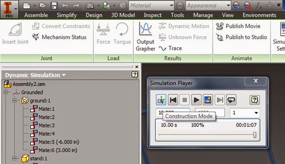
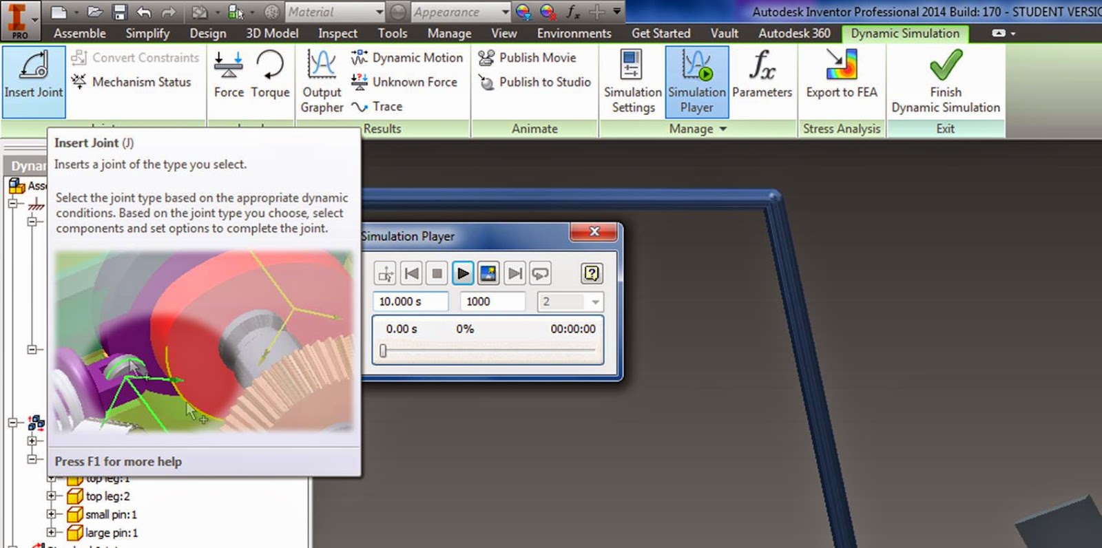
Environments → Dynamic Simulation

Simulation player → Construction mode
Upper left hand icon in simulation player - you have to be in construction mode in order to edit anything.
Assign gravity to act down:(Just right click on the gravity apple in the left hand menu)

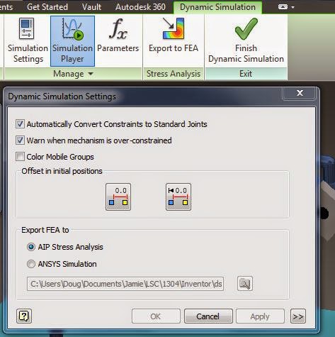
Note: Your simulation settings should be set to automatically convert constraints to standard joints:
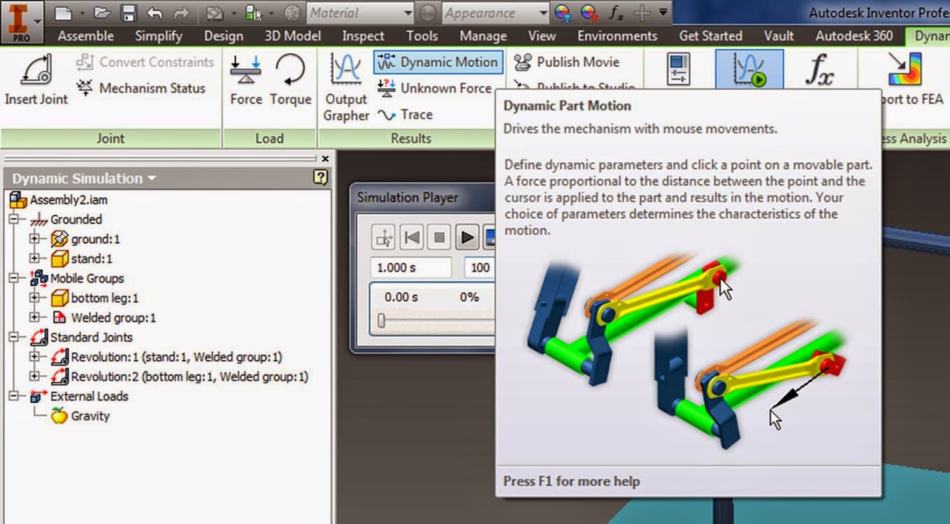
Look for the joints that were created from your constraints:

Test out your dynamic motion:
Adjust parts as needed (I changed the frame size for increased motion)

Once you have the dynamic motion all set, go ahead and run your simulation.
Click the "Construction Mode" button on the upper left hand corner of your simulation to go back and edit joints, forces, etc. to get the motion working correctly.
Click on "Output Grapher" then right click and add a tracer:

Collect output for Traj, Vel, Acc, change the tracer color to something that shows up (like yellow) and click on a point to trace (like the end of the pendulum)

Run the simulation with your tracer on, open up the graphs (+), check what you want to see.

Adding constraints:
Right now, my pendulum can go through the bar that is holding it up. Let's add a constraint to fix this:

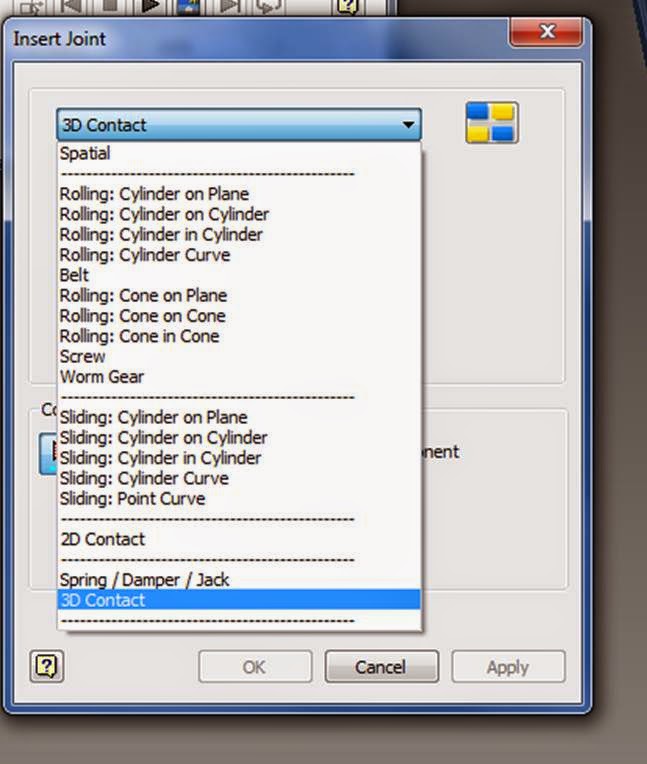
Hit the construction button on your simulation player, then select "Insert Joint:
You can click on any of the constraints, and see an animation of what type of constrain it is - have a look around at all the different constraints, then choose 3D contact.
Select component 1:
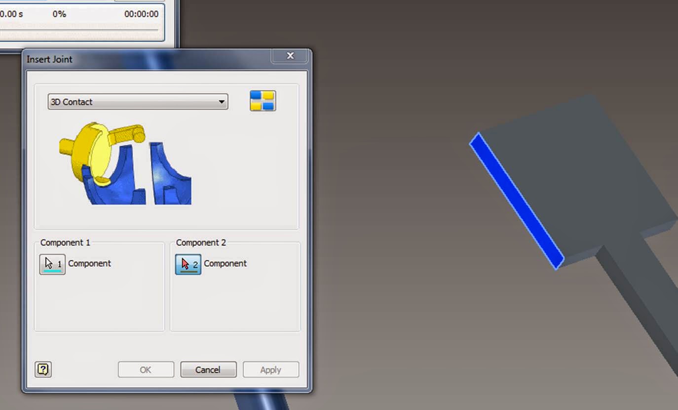
Select component 2:

Run the simulation with the pendulum starting in a high position:

Notice that now your pendulum will bounce off of, rather than travel through, the bar that is holding it up.

Play around with it! Look at the velocity and acceleration graphs, or create some new systems to play with!
Work on your semester project - it's due next Thursday!!!
:
Saturday, April 19, 2014
FEA
FEM Finite Element Method:
Breaks large complex geometries into small connected elements in order to analyze things like strength properties.
Connect nodes with springs:


Simple Stress Strain diagram:

Materials behave like simple linear springs within their elastic region.


Some example problems relating Young's Modulus to spring forces:
https://notendur.hi.is/eme1/skoli/edl_h05/masteringphysics/11/youngsModulus.htm
Failure Criteria:
von Mises criterion
- reasonable estimation of fatigue failure, especially in cases of repeated tensile and tensile-shear loading
states that failure occurs when the energy of distortion reaches the same energy for yield/failure in uniaxial tension. Mathematically, this is expressed as,

principle stresses:

http://demonstrations.wolfram.com/MohrsCircleAndFailureCriterionForPlanarStressStates/
Review Mechanics of Materials notes:
http://engr1304.blogspot.com/2014/03/mechanics-of-materials.html
Inventor Stress Analysis:
right click on a part in your assembly, open
Go to: Environment - Stress Analysis

Create Simulation:

Single Point Static Analysis

OK:


First, set the material your part is made out of:

Next, add a constraint, or grounded point for your part:


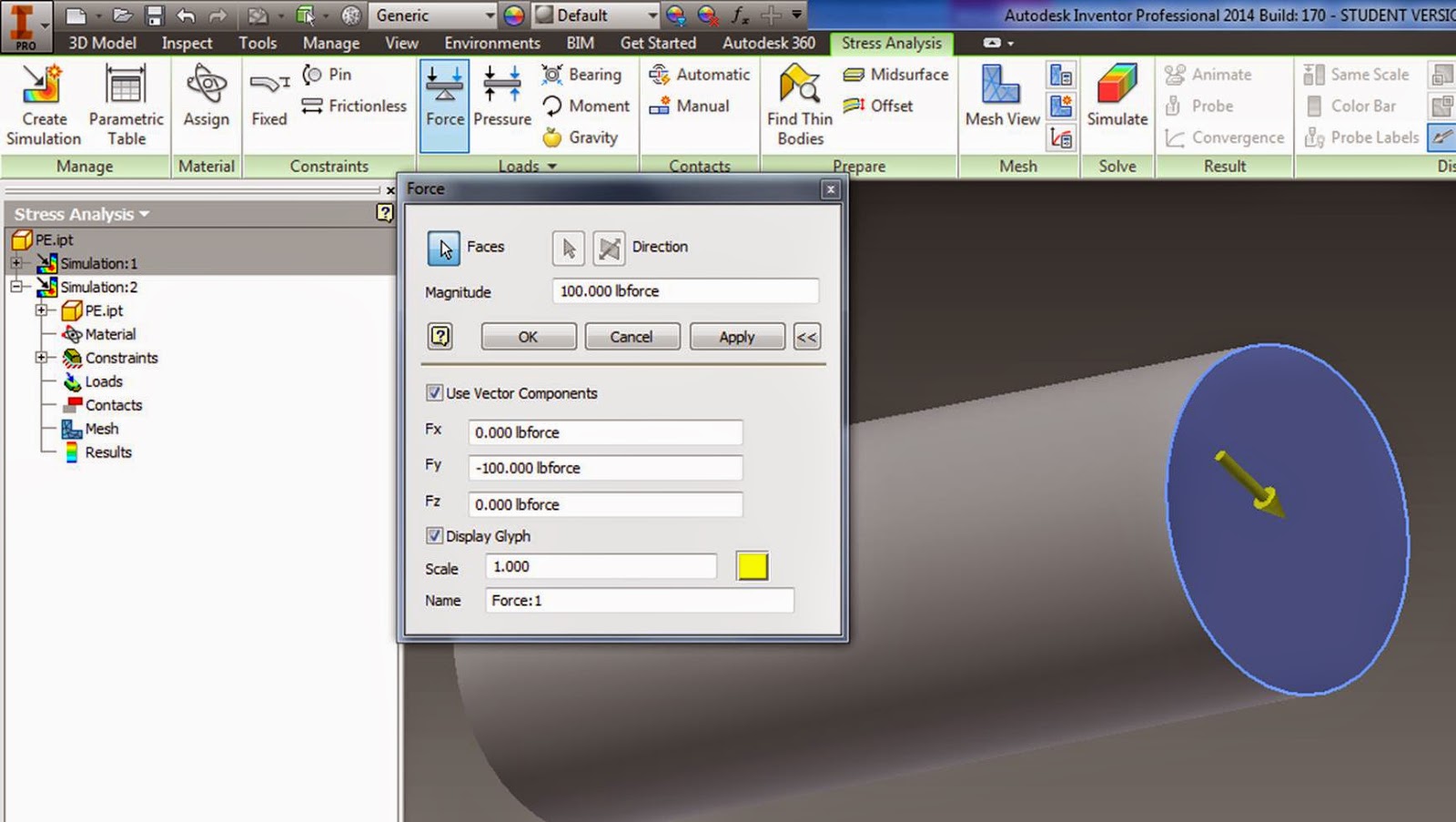
Check "Use vector components" to snap forces to a world coordinate, or just snap it to a direction on your part.

Create a mesh:

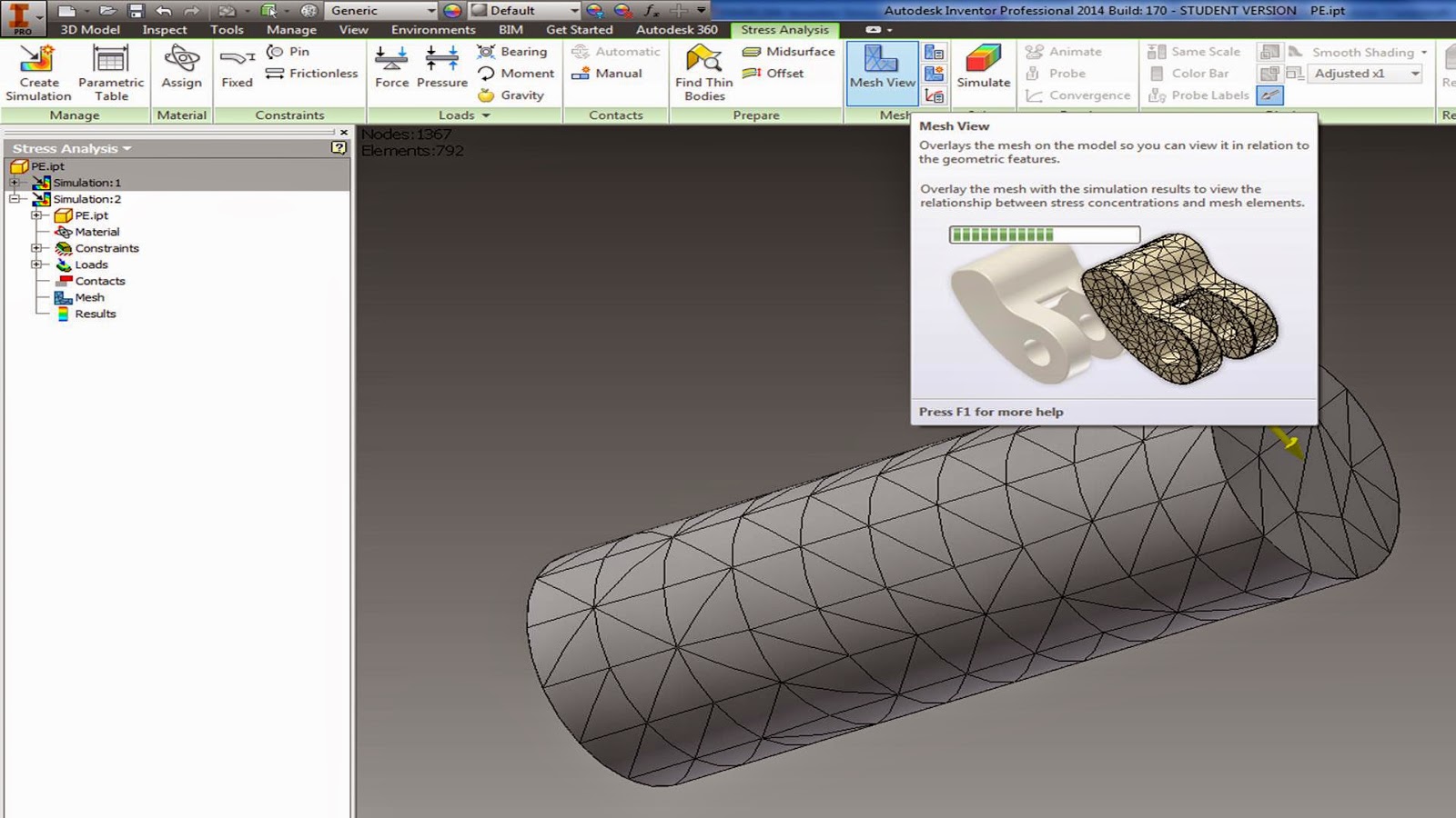
if you want to change the mesh size:


Right click on the Red lightning bolt next to Mesh, select update mesh:

Run simulation:

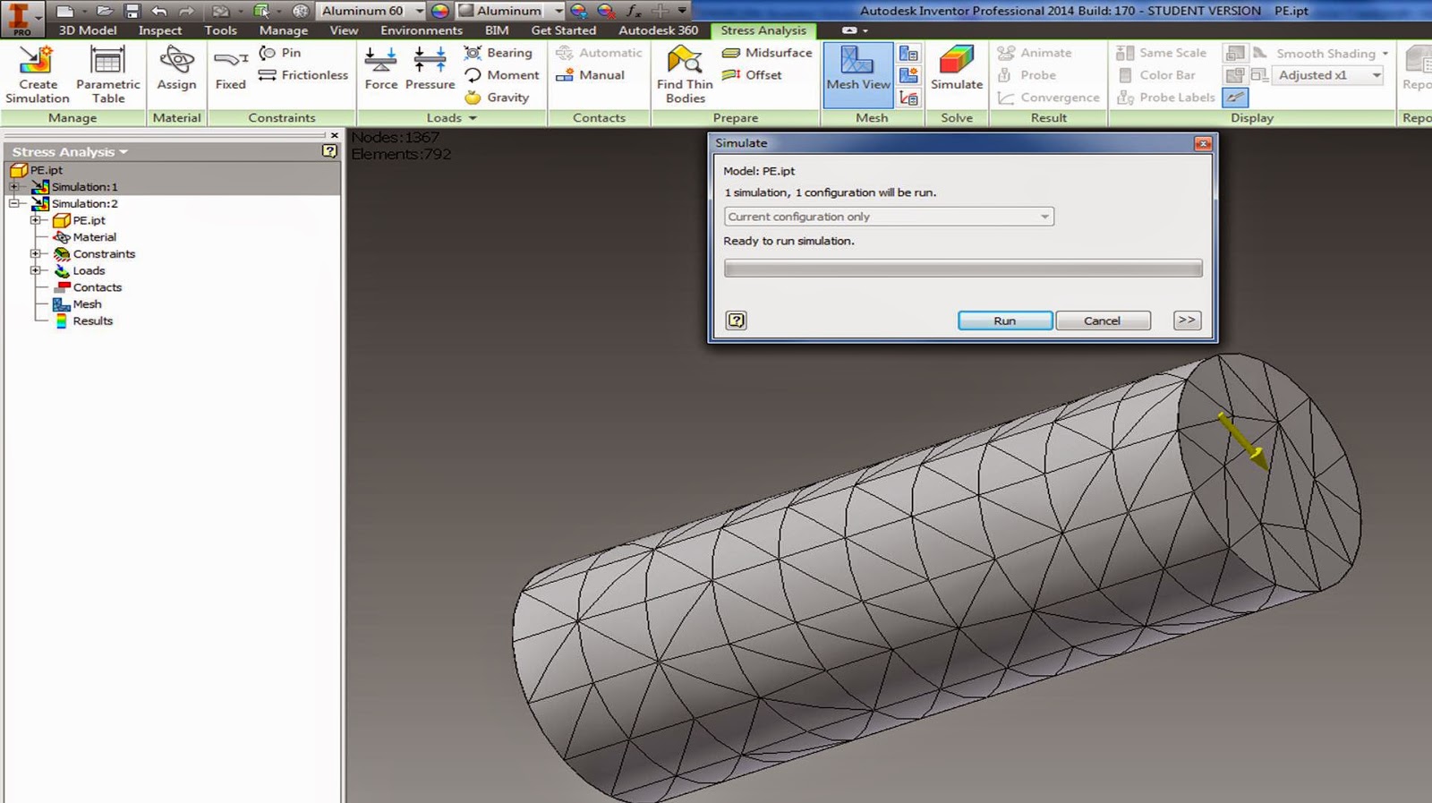
Hit Run
Red areas are failure zones.

Note: the smaller your mesh size, the longer it will take to run.
Experiment with a few different parts in your assembly, and with a few different materials. Try to understand what the "weak link" is.


After the first simulation, look at where the highest stresses are, and tighten up your mesh in those areas.

Change the scale for the displacement to better see where deformation is occurring.

Displacement scale = 5

Displacement scale = 0.5

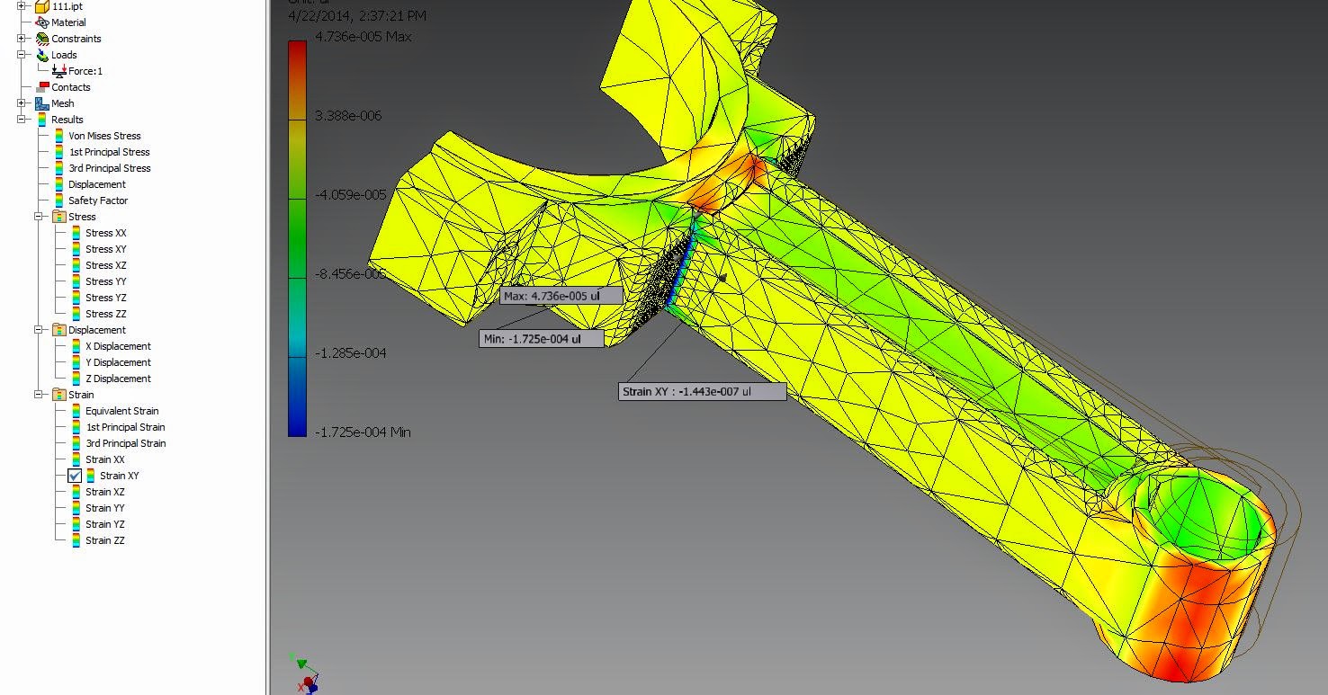
Find the min and max stresses in your system:


Use the probe to find and label information for any point you click on:


Animate the forces being applied:

Have a look through all of the different stresses and strain it has calculated for you, just double click in the menu on what you want to look at:

View the Safety Factor:
Note: Safety factor less than one at any point in your object means it will fail.

Set up multiple simulations in order to compare different loads and designs
Right click → copy simulation:

Now you have two identical simulations.
Go under your copied simulation (simulation 2) open up your parts, and modify them.
Go under your copied simulation (simulation 2) open up your parts, and modify them.


Modified part:

After you have modified your part, go back and re-generate your mesh, and re-run your simulation.

Comparison of stresses with fillets (above) to without fillets (below) show that the stress is more evenly distributed with rounded corners. A significantly smaller Max stress is achieved through rounding out the corners.

Assignment:
Use the snipping tool:
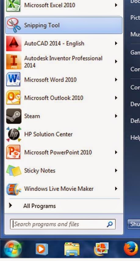
To save pictures of your results.
a) Compare the stress and strain in your part if it is made out of different materials.
b) Modify your part somehow to lower the maximum stress under constant loading conditions.
Write a short memo containing snips from your stress analysis, your assembly, and a few paragraphs discussing part failure in engines, material selection, and design considerations.
Email me your memo (don't print it out, the black and white printer will not show the colors).
Subscribe to:
Posts (Atom)