FEM Finite Element Method:
Breaks large complex geometries into small connected elements in order to analyze things like strength properties.
Connect nodes with springs:


Simple Stress Strain diagram:

Materials behave like simple linear springs within their elastic region.


Some example problems relating Young's Modulus to spring forces:
https://notendur.hi.is/eme1/skoli/edl_h05/masteringphysics/11/youngsModulus.htm
Failure Criteria:
von Mises criterion
- reasonable estimation of fatigue failure, especially in cases of repeated tensile and tensile-shear loading
states that failure occurs when the energy of distortion reaches the same energy for yield/failure in uniaxial tension. Mathematically, this is expressed as,

principle stresses:

http://demonstrations.wolfram.com/MohrsCircleAndFailureCriterionForPlanarStressStates/
Review Mechanics of Materials notes:
http://engr1304.blogspot.com/2014/03/mechanics-of-materials.html
Inventor Stress Analysis:
right click on a part in your assembly, open
Go to: Environment - Stress Analysis

Create Simulation:

Single Point Static Analysis

OK:


First, set the material your part is made out of:

Next, add a constraint, or grounded point for your part:


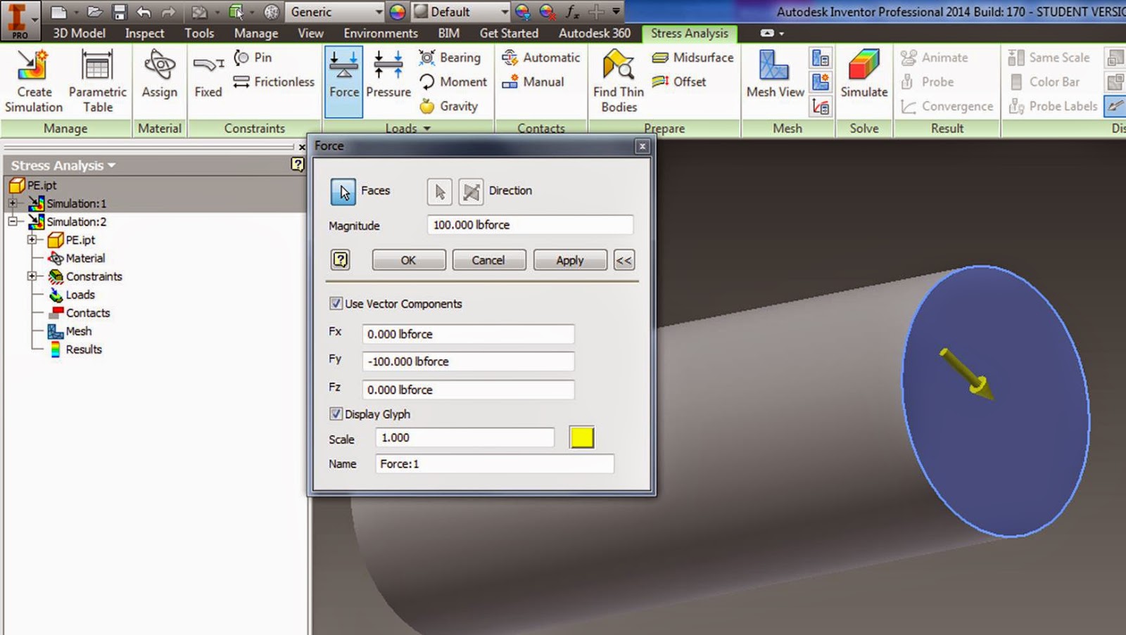
Check "Use vector components" to snap forces to a world coordinate, or just snap it to a direction on your part.

Create a mesh:

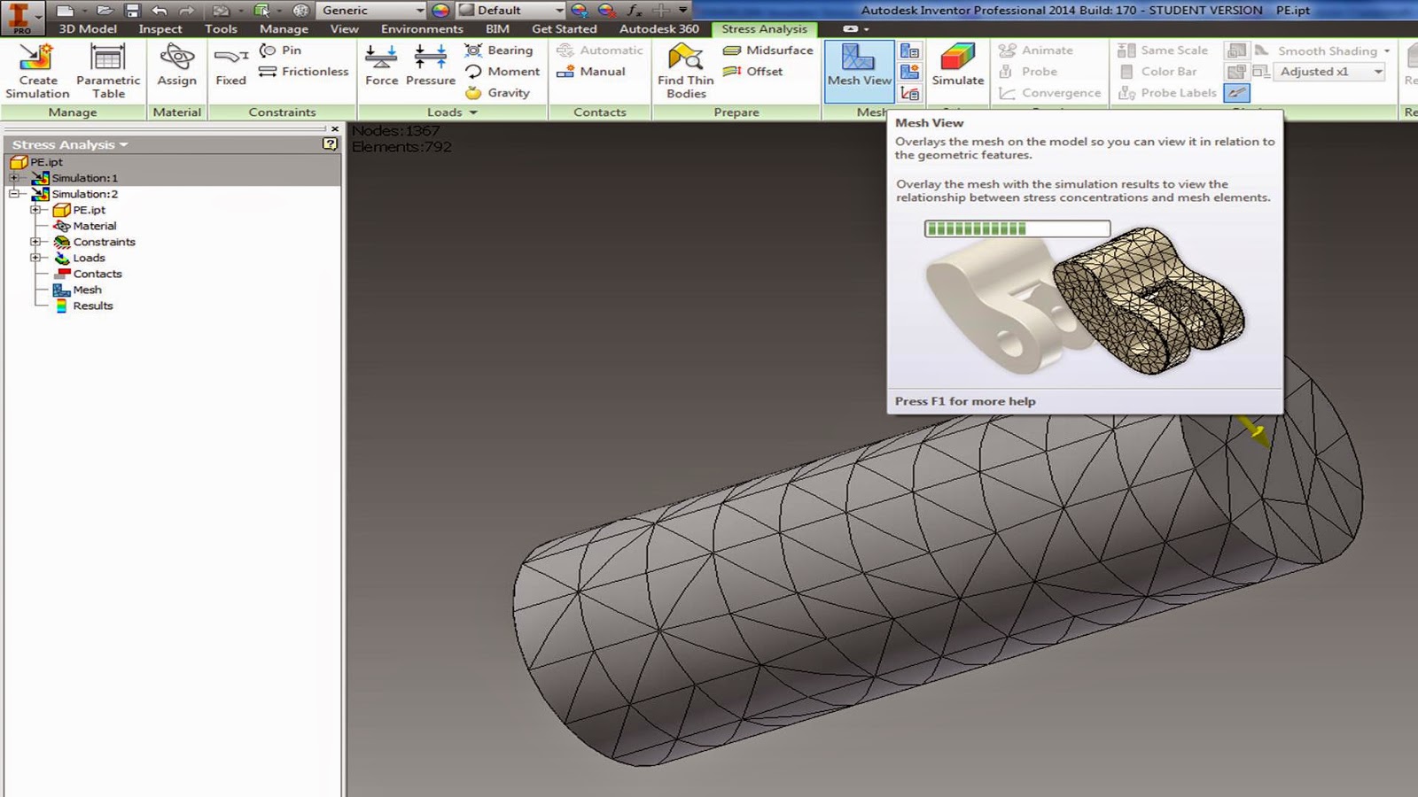
if you want to change the mesh size:


Right click on the Red lightning bolt next to Mesh, select update mesh:

Run simulation:

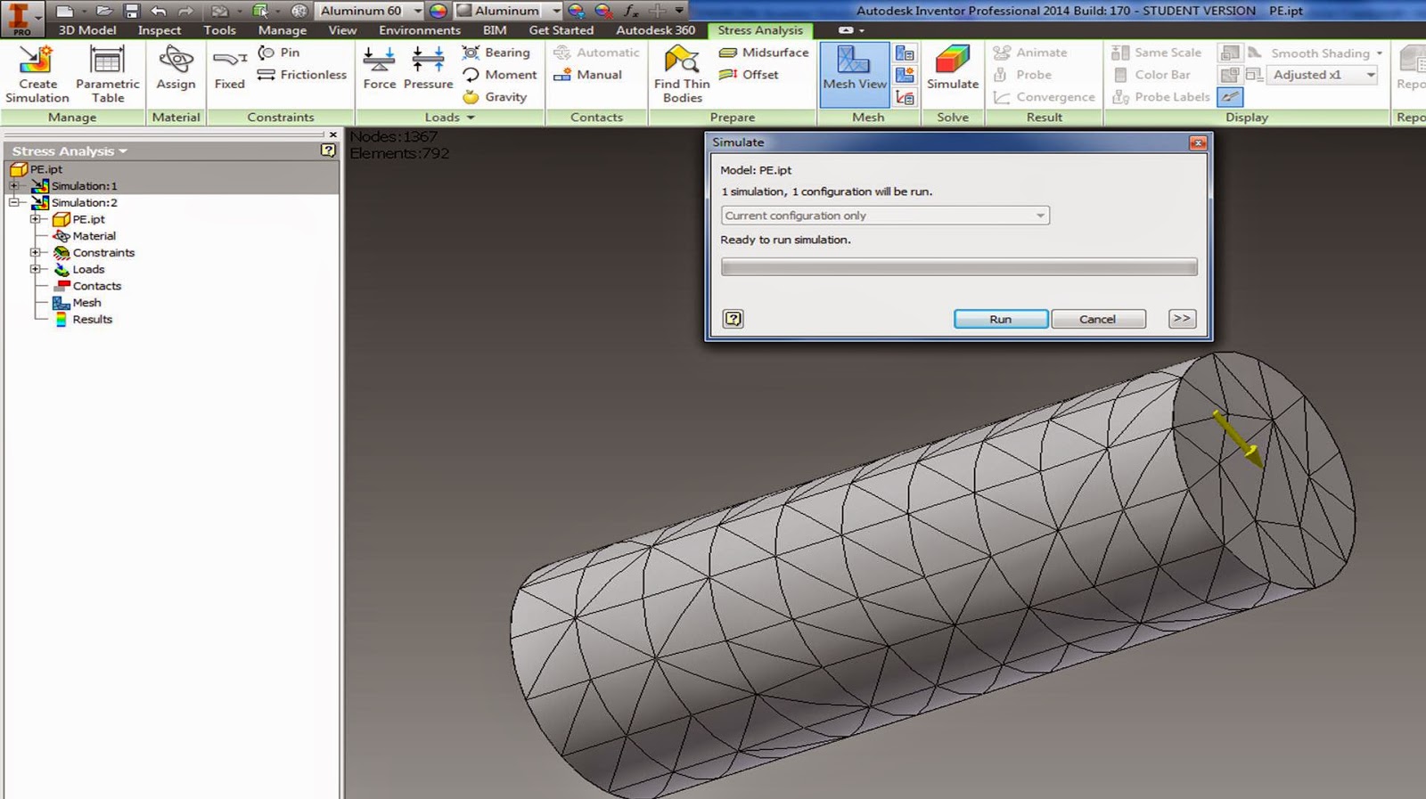
Hit Run
Red areas are failure zones.

Note: the smaller your mesh size, the longer it will take to run.
Experiment with a few different parts in your assembly, and with a few different materials. Try to understand what the "weak link" is.


After the first simulation, look at where the highest stresses are, and tighten up your mesh in those areas.

Change the scale for the displacement to better see where deformation is occurring.

Displacement scale = 5

Displacement scale = 0.5

Find the min and max stresses in your system:


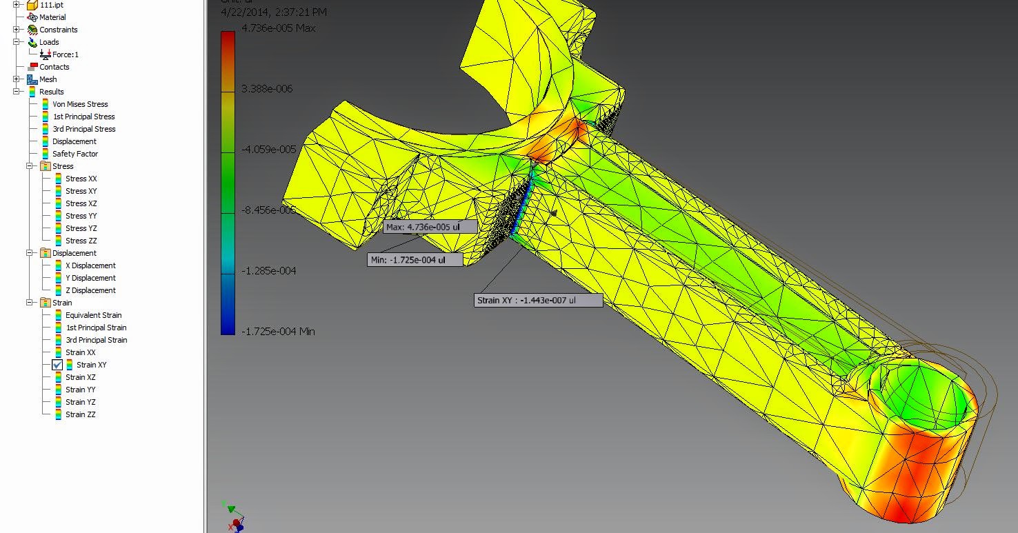
Use the probe to find and label information for any point you click on:


Animate the forces being applied:

Have a look through all of the different stresses and strain it has calculated for you, just double click in the menu on what you want to look at:

View the Safety Factor:
Note: Safety factor less than one at any point in your object means it will fail.

Set up multiple simulations in order to compare different loads and designs
Right click → copy simulation:

Now you have two identical simulations.
Go under your copied simulation (simulation 2) open up your parts, and modify them.
Go under your copied simulation (simulation 2) open up your parts, and modify them.


Modified part:

After you have modified your part, go back and re-generate your mesh, and re-run your simulation.

Comparison of stresses with fillets (above) to without fillets (below) show that the stress is more evenly distributed with rounded corners. A significantly smaller Max stress is achieved through rounding out the corners.

Assignment:
Use the snipping tool:
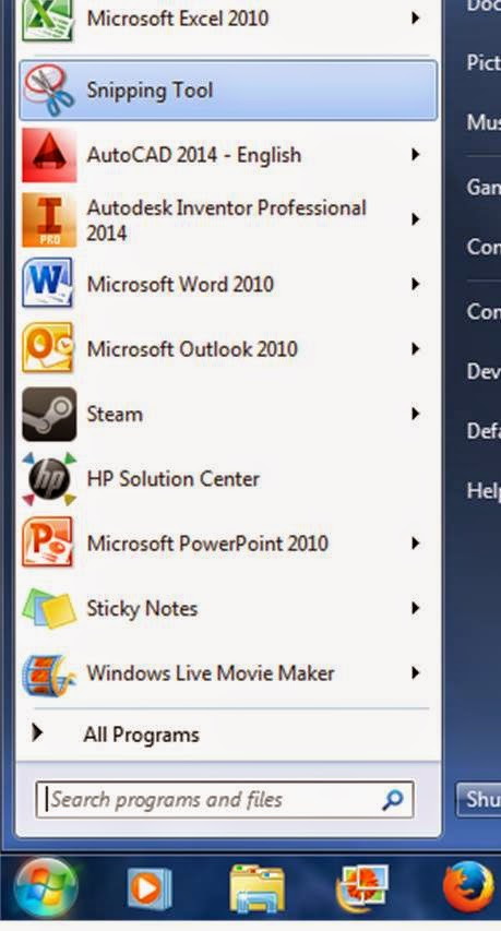
To save pictures of your results.
a) Compare the stress and strain in your part if it is made out of different materials.
b) Modify your part somehow to lower the maximum stress under constant loading conditions.
Write a short memo containing snips from your stress analysis, your assembly, and a few paragraphs discussing part failure in engines, material selection, and design considerations.
Email me your memo (don't print it out, the black and white printer will not show the colors).
No comments:
Post a Comment